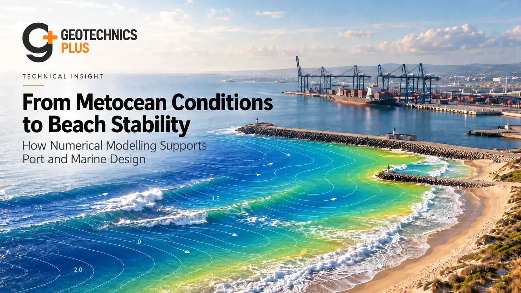
Port and marine projects are exposed to a chain of interacting processes: offshore wind and waves generate the forcing, tides and storm surge control water levels, waves transform as they approach the coast, currents redistribute sediment, and the shoreline or seabed responds.
For that reason, a robust coastal design workflow often follows three linked stages:
- Metocean and water-level assessment
- Wave transformation and hydrodynamic modelling
- Beach, shoreline and seabed stability assessment
These stages should not be treated as separate reports. They are part of one engineering system. The quality of the final design depends on whether the inputs, numerical models and engineering interpretation remain consistent from offshore boundary conditions to the structure, beach or seabed being assessed.
Modern software such as Delft3D, MIKE 21/3, SWAN, XBeach and other coastal and CFD tools can simulate these processes in considerable detail. But the software is not the engineering. Model selection, calibration, boundary conditions, uncertainty and interpretation are what determine whether the results are useful.
1. Why metocean assessment is the starting point
Every marine design begins with environmental forcing. The first task is to establish the combinations of wind, waves, tides, surge and currents that the project may experience during construction, operation and extreme events.
A typical metocean assessment may consider:
- wind speed and direction;
- significant wave height, peak period and directional wave spectrum;
- astronomical tide;
- storm surge and residual water level;
- sea-level variability and long-term sea-level rise;
- currents generated by tides, wind, rivers and waves;
- seasonality and storm persistence;
- extreme-value statistics and return periods; and
- joint probability of coincident waves and water levels.
The design question is rarely just “what is the 100-year wave?” A structure may be more sensitive to the combination of moderate waves and unusually high water level, to a directional storm that aligns with a harbour entrance, or to a long-period swell that penetrates farther into a basin.
For geotechnical and marine-structure design, water level can also alter the effective height of wave loading, freeboard, overtopping, scour potential, uplift and the portion of a retaining system exposed to cyclic hydraulic action.
2. Extreme conditions should be defined for the decision being made
Different design checks require different environmental conditions.
A berth operability assessment may be governed by relatively frequent wave conditions. Breakwater stability may require a much rarer storm. Dredging or temporary works may be controlled by a short seasonal exposure window. A shoreline stability assessment may depend on repeated annual events rather than one extreme storm.
The metocean basis should therefore distinguish between:
- operational conditions;
- frequent service-level events;
- design storms;
- extreme or accidental events;
- temporary construction conditions; and
- future climate or sea-level scenarios where relevant.
Using one return-period condition for every design question can lead either to unnecessary conservatism or to missed risk.
3. Offshore waves are not the waves that reach the structure
Wave conditions change as they move from deep water toward a port, beach or marine structure.
Important transformation processes include:
- shoaling as water depth decreases;
- refraction as wave celerity changes across bathymetric contours;
- diffraction around breakwaters, headlands and harbour entrances;
- breaking in shallow water;
- bottom friction over shallow seabeds;
- whitecapping and depth-induced dissipation;
- wave-current interaction; and
- reflection from coastal and harbour structures.
The design wave at a quay wall, revetment, beach or pile-supported berth can therefore be materially different from the offshore wave climate.
This is where spectral wave models become important. Tools such as SWAN, Delft3D Waves and MIKE 21 Spectral Waves can transfer offshore wave spectra through complex bathymetry and into nearshore or harbour environments while representing the dominant transformation processes.
4. Wave transformation should be checked against the actual port geometry
Port layouts strongly influence local wave conditions.
Breakwater orientation, entrance width, dredged channels, reclamation edges, quay alignments and berth pockets can change how wave energy is refracted, diffracted and reflected.
A model used only on the natural pre-project bathymetry may therefore miss the conditions that will exist after construction.
For major schemes, it is often necessary to model several layouts and ask:
- Does the entrance admit excessive wave energy?
- Are particular berths exposed to one dominant direction?
- Does a dredged channel focus or defocus waves?
- Will a new breakwater create unacceptable reflection or agitation?
- Does reclamation alter circulation or sediment pathways?
- Are long-period motions important inside the harbour?
Wave modelling becomes most valuable when it is used as a design tool, not simply as a final verification exercise.
5. Hydrodynamic modelling adds currents and water-level response
Wave transformation alone does not describe the marine environment. Hydrodynamic models are used to simulate water levels and currents under tidal, meteorological and river forcing.
Depending on the project, a 2D depth-averaged model may be sufficient. More complex estuaries, stratified basins or outfall studies may require 3D modelling.
Typical outputs include:
- time-varying water levels;
- current speed and direction;
- storm-surge response;
- circulation patterns;
- residence time and exchange;
- wave-induced currents;
- flow around structures and reclamation; and
- velocity changes caused by dredging or channel modification.
MIKE 21/3 and Delft3D Flexible Mesh are examples of integrated modelling suites that can represent hydrodynamics, waves, sediment transport and morphology in coupled workflows.
6. When should wave and current models be coupled?
Wave and current interaction becomes important where each process materially changes the other.
Examples include:
- surf zones where breaking waves generate strong longshore currents;
- tidal entrances where currents modify wave propagation;
- navigation channels with strong ebb or flood flows;
- river mouths and estuaries;
- locations subject to wave-driven circulation around breakwaters; and
- sediment transport studies where both waves and currents contribute to bed shear stress.
In these settings, running a wave model and a current model independently can miss the combined forcing that controls erosion, deposition or navigation conditions.
7. Beach stability is fundamentally a sediment-balance problem
A beach does not remain stable because every grain of sand stays in place. It remains stable when sediment transport over the relevant time scale is compatible with the desired shoreline position and beach profile.
Beach and shoreline assessment therefore considers:
- alongshore sediment transport;
- cross-shore sediment transport;
- storm erosion and post-storm recovery;
- sediment supply and losses;
- beach material grading;
- wave angle and breaking pattern;
- currents and tidal range;
- headlands, groynes and breakwaters;
- dredging and sediment bypassing; and
- sea-level change.
The key question is often not “is the beach stable?” but “under what forcing, over what time scale, and with what sediment-management intervention can the desired beach geometry be maintained?”
8. Numerical morphology models help test shoreline response
Where shoreline change is a material project risk, numerical morphology models can be used to estimate how sediment pathways and bathymetry may evolve.
Delft3D can simulate coupled flow, waves, sediment transport and morphology. MIKE 21 includes hydrodynamic, spectral-wave, sand-transport and shoreline-morphology modules. XBeach is particularly useful for storm-scale nearshore hydrodynamics and morphodynamic response, including erosion, overwash and scour.
These tools can support questions such as:
- Will a new breakwater interrupt littoral drift?
- Could the downdrift shoreline erode?
- Will a navigation channel experience excessive infilling?
- How much nourishment may be required?
- Could a storm remove the design beach profile?
- Will a dredged pocket change local currents enough to trigger erosion?
- Where is sediment likely to accumulate?
Long-term morphology should be interpreted cautiously because uncertainty accumulates through both environmental forcing and model formulation. Scenario comparison is often more reliable than treating one future shoreline position as a precise prediction.
9. The link to geotechnical design is often underestimated
Hydrodynamic and coastal modelling directly affects geotechnical and geo-structural design.
For example:
Scour: predicted waves and currents influence local and general scour around piles, quay walls, bridge piers and revetments.
Quay walls and retaining structures: external water level, wave loading, cyclic water pressure and seabed lowering can affect stability and deformation.
Breakwaters and revetments: wave climate controls armour size, toe stability, filter design and overtopping performance.
Dredging: changes in seabed elevation can reduce passive resistance, alter groundwater gradients and change slope stability.
Reclamation: hydrodynamic changes can create erosion or deposition at the edge of fill platforms and alter shoreline protection requirements.
Foundations: scour depth and seabed mobility affect pile unsupported length, lateral response and long-term durability.
Beach nourishment and coastal protection: hydraulic performance must be integrated with settlement, subgrade behaviour and constructability.
The strongest marine designs therefore connect coastal modelling outputs directly to the geotechnical design basis rather than treating them as parallel disciplines.
10. CFD has a role—but only at the right scale
Large-area coastal problems are usually addressed with depth-averaged or spectral models because they can efficiently represent kilometres of coastline and long simulation periods.
Computational Fluid Dynamics, including tools based on Navier-Stokes or volume-of-fluid formulations, becomes useful where local flow physics must be resolved in greater detail.
Examples include:
- wave impact on complex structures;
- local flow around piles or caissons;
- overtopping and splash;
- jetting and propeller wash;
- local scour processes;
- highly three-dimensional harbour features; and
- special hydraulic structures.
The model domain and physics should match the decision. Using CFD for a regional wave-climate problem may be computationally inefficient; using a large-scale spectral model for a highly local three-dimensional impact problem may be too simplified.
11. Calibration and validation matter more than software brand
A technically strong numerical model should reproduce the important observed behaviour before it is trusted for design scenarios.
Depending on the study, calibration and validation data may include:
- tide-gauge water levels;
- ADCP current measurements;
- wave-buoy or pressure-sensor data;
- wind records;
- bathymetric surveys;
- shoreline positions from aerial imagery or LiDAR;
- sediment samples;
- historical dredging volumes; and
- observed erosion or deposition patterns.
A complex model with weak calibration is generally less defensible than a simpler model that reproduces the controlling site processes.
12. Grid resolution, bathymetry and boundaries can control the answer
Numerical output can look smooth and precise even when the model inputs are weak.
Particular attention should be paid to:
- quality and date of bathymetric data;
- representation of dredged slopes and structures;
- mesh refinement around entrances and coastal features;
- offshore boundary location;
- wave-spectrum definition;
- tide and surge boundary conditions;
- bed roughness;
- sediment properties; and
- treatment of dry and wet cells.
Model sensitivity should be tested where these assumptions materially influence the design output.
13. Climate change should enter through the physical parameters
Climate resilience is most useful when it is translated into parameters that affect the engineering model.
For port and marine studies this may include:
- future mean sea level;
- changes in extreme water level;
- changes in storm intensity or wave climate where supported;
- increased frequency of overtopping;
- modified shoreline equilibrium; and
- changes in sediment transport or maintenance dredging.
Rather than adding a generic climate-change factor at the end, future scenarios should be propagated through the same hydrodynamic, wave and morphology workflow used for the present-day design.
14. What should a fit-for-purpose modelling study deliver?
A useful port or coastal modelling study should not stop at contour plots.
Its outputs should answer specific design questions, for example:
- design wave conditions at each structure or berth;
- water levels for stability and overtopping checks;
- current fields affecting navigation or sediment transport;
- harbour agitation or berth-operability conditions;
- erosion and deposition hotspots;
- expected shoreline response;
- scour-design inputs;
- maintenance-dredging risk;
- comparison of layout alternatives; and
- uncertainty ranges relevant to the decision.
The numerical model becomes valuable when it changes a design decision, clarifies a risk or avoids unnecessary construction—not simply when it produces attractive graphics.
15. A practical integrated workflow
For many port and marine developments, a defensible workflow is:
- Define the engineering decisions. Identify what needs to be designed or compared.
- Establish metocean and water-level conditions. Separate operational, design and extreme states.
- Transform offshore waves to the project area. Represent actual bathymetry and proposed layouts.
- Model hydrodynamics where currents and water levels matter.
- Couple waves and currents where their interaction affects sediment or structures.
- Assess sediment transport, beach stability and morphology.
- Calibrate and test sensitivity.
- Transfer the outputs into geotechnical and structural design.
- Test future and construction-stage scenarios where relevant.
- Document uncertainty in terms that support a decision.
Conclusion
Port and marine design is strongest when metocean assessment, wave transformation, hydrodynamics, sediment transport and geotechnical response are treated as one connected system.
Offshore wave data alone are not enough. The design depends on how waves and water levels transform through the project bathymetry, how currents redistribute sediment, how the beach or seabed responds, and how those changes affect structures and foundations.
Advanced numerical modelling provides a powerful way to connect these processes—but only when the model is built around the engineering question, calibrated against the site and interpreted with an understanding of the physical mechanisms involved.
The objective is not to use the most sophisticated software available. It is to use the right level of modelling to make better decisions about layout, stability, operability, resilience and long-term performance.
References and further guidance
- U.S. Army Corps of Engineers. EM 1110-2-1100, Coastal Engineering Manual.
- Deltares. Delft3D Flexible Mesh Suite.
- Deltares. XBeach.
- DHI. MIKE 21 and MIKE 3.
- DHI. MIKE 21 Spectral Waves.
- DHI. MIKE 21 Shoreline Morphology.